Natural Gas Dehydration Unit With TEG
Process modeling and simulation with ProSimPlus
|
|
|
The model
This process is the “traditional” Triethylene Glycol (TEG) based dehydration process and represent a unit with gas absorption and extraction solvent regeneration.
The objective is to reduce the amount of water in the natural gas with TEG, used as the extraction solvent.
The process utilizes a closed propane refrigeration loop (green streams) around a brazed plate fin heat exchanger.
The description of the process follows.
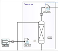 The wet gas feeds the contactor D200 (stream 1) at 71 bar gage. This column absorbs a part of the water in the gas in the Triethylene Glycol (TEG) mixture.
At the end of the regeneration loop, the lean TEG feeds the top part of the contactor (stream 16) and absorbs water. Rich TEG leaves the bottom (stream 3) by level control and is depressurized to 5 bar gage (valve V200).
The wet gas feeds the contactor D200 (stream 1) at 71 bar gage. This column absorbs a part of the water in the gas in the Triethylene Glycol (TEG) mixture.
At the end of the regeneration loop, the lean TEG feeds the top part of the contactor (stream 16) and absorbs water. Rich TEG leaves the bottom (stream 3) by level control and is depressurized to 5 bar gage (valve V200).
The rich stream flows through a cartridge filter (F200 A/B) to remove solid particles coming from corrosion or TEG degradation. These solid particles and degradation are not taken into account in this model and consequently, the filtration does not have any impact in terms of simulation and is not represented.
 Once filtered, this flow is used as cold fluid of the condenser (E200) of the TEG regeneration column (C201). In the simulation this condenser is represented separately from the column.
The amount of heat to be removed in the C201 column condenser is transferred through an information stream (blue dotted line) in the heat exchanger module E200.
Once filtered, this flow is used as cold fluid of the condenser (E200) of the TEG regeneration column (C201). In the simulation this condenser is represented separately from the column.
The amount of heat to be removed in the C201 column condenser is transferred through an information stream (blue dotted line) in the heat exchanger module E200.
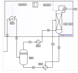
The wet TEG then enters a flash tank B200 (stream 5) in which gaseous hydrocarbons that were absorbed along with the water in the contactor are vaporized.
These hydrocarbons are heated in heat exchanger E204 (stream 7) and used as stripping fluid in the stripper C202 (stream 9).
The liquid phase heated in the heat exchanger E202 (stream 6) then feeds the regenerator C201 head (stream 11). This column is used to strip water from the TEG and operates at atmospheric pressure.
Waste gases consisting of water and the hydrocarbons dissolved in the TEG, leave the regenerator at the top. The liquid bottom stream feeds the stripping column C202.
This column decreases of the TEG water concentration by stripping using hydrocarbons vapors from B200.
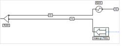 Lean TEG (stream 8) is then sent from the bottom of the column to storage tank R200. This storage tank has no meaning in terms of steady-state simulation but allows the regulation of the TEG flow.
Consequently, it is represented by a mixer module. The TEG make-up (stream 14) is required to compensate the losses due to gas entrainment or degradation. Lean TEG is then pumped in P200 A/B and feed the contactor D200 head (stream 16).
Lean TEG (stream 8) is then sent from the bottom of the column to storage tank R200. This storage tank has no meaning in terms of steady-state simulation but allows the regulation of the TEG flow.
Consequently, it is represented by a mixer module. The TEG make-up (stream 14) is required to compensate the losses due to gas entrainment or degradation. Lean TEG is then pumped in P200 A/B and feed the contactor D200 head (stream 16).
Modeling and simulation tips
the top column C201 condenser has been separated in the simulation flowsheet: the heat duty removed from the condenser is transferred through an information stream to the heat exchanger module E200.
The required conversion is made by information stream handler.
C201 and C202 columns are represented with a unique column module as they are installed in series. The C201 reboiler is set in this module as an intermediate tray boiler. This simplifies the simulation flow scheme but it’s not mandatory. Using s distillation column module for C201 and a stripper module for C202 connected in series would have provided the same results.
The TEG flowrate in the loop is fixed by initializing the flash drum B200 inlet stream (stream 5). From the knowledge of this flowrate, it is possible to calculate B200, C201 / C202 and the TEG feed to contactor D200. Initialization is set in order to obtain a dry gas dew point at -40°C.
Additional calculations
Windows Script modules provide a VBS(Visual Basic Script) environment in which the user can code calculation modules that will be executed during the simulation.
This example uses three of these modules. Modules Dew C_1 and Dew C_17, located on the wet gas stream and on the dry gas stream calculate the water dew point of their respective streams.
The third module called TEG loss is used to calculate the required TEG make-up from the TEG losses in the dry gas and the waste gas.
|
Components
Components taken into account in the simulation are extracted from the ProSimPlus standard database:
| Name | Chemical formula |
| Methane | CH4 |
| Ethane | C2H6 |
| Propane | C3H8 |
| n-butane | C4H10 |
| Isobutane | C4H10 |
| n-pentane | C5H12 |
| Isopentane | C5H12 |
| n-hexane | C6H14 |
| n-heptane | C7H16 |
| n-octane | C8H18 |
| n-nonane | C9H20 |
| n-decane | C10H22 |
| n-undecane | C11H24 |
| n-dodecane | C12H26 |
| Nitrogen | N2 |
| Carbon dioxide | CO2 |
| Water | H20 |
| Triethylene Glycol | C6H14O4 |
Thermodynamic model
Considering the temperatures and pressures of the contactor, an equation of state approach has been chosen, allowing the accurate calculation of the thermodynamics functions (fugacities, enthalpies, entropies….) at conditions close to critical conditions. As polar components are also present (water and TEG in particular), a complex mixing rule has been used in order to use an equation of state approach with this type of components.
The equation of state selected is the Peng-Robinson equation of state with the mixing rule MHV2 proposed by Michelsen and al. The model for the excess enthalpy calculation is UNIQUAC.
The binaries interaction parameters have been regressed in MS-Excel using Simulis Thermodynamics.
|
ADDITIONAL INFORMATION
Contact ProSim by e-mail (sales @ prosim.net) or through the contact page from ProSim website (click on the button):

|
|
|


